

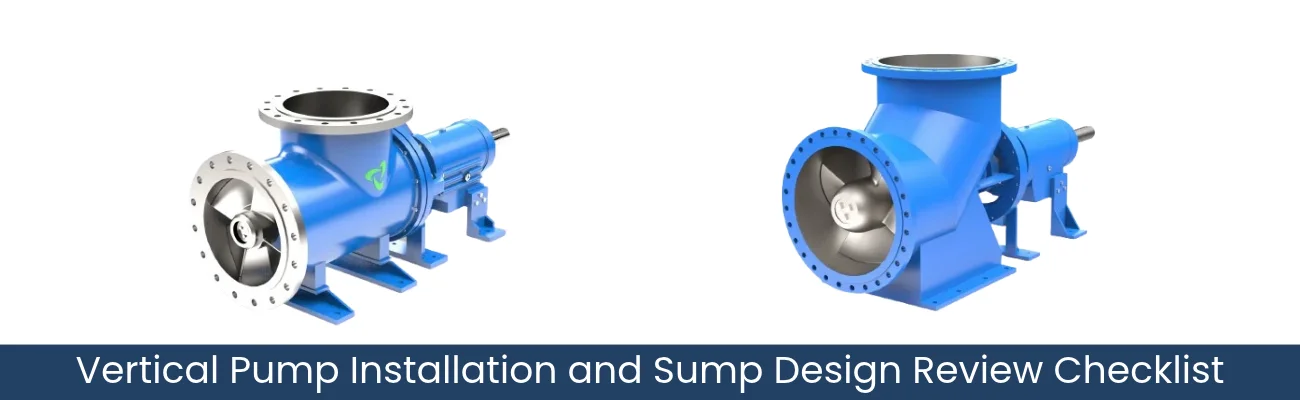
Axial Flow Pump Intake Design: Sump Layout, Submergence and Air Entry
An Axial Flow Pump is chosen when a station must move large volumes of liquid against a low head. Raw water intake, cooling water circulation, stormwater removal, flood control and irrigation are typical examples.
In a sump installation, the pump is only one part of the system. Axial flow pump intake design considers the incoming flow, while pump sump design establishes the surrounding arrangement. Pump submergence changes with the operating liquid level. Air carried into the liquid entering the pump is described as pump air entrainment. These conditions need review alongside pump selection.
Propeller Pumps offers a vertical axial flow pump designed for wet pit, sump and open channel installations. This article covers that vertical arrangement and the site information needed to review it.
Axial Flow Pump Intake Design: Mapping the Approach Flow
Begin with the route the liquid takes before it reaches the pump. The upstream arrangement should be reviewed together with the sump itself.
Document the following:
- Incoming channels or pipes: number, size and entry points.
- Entry direction: in line with the pump, from the side, or from above.
- Bends and transitions: changes in direction, width or depth just upstream.
- Relative position: distance and alignment between the flow entry and the pump.
- Flow sources: gravity channels, pumped inflows or several sources at once.
Mark these features on one drawing so the complete path is visible at a glance. For an existing station, check whether the available drawings reflect construction changes.
If the layout raises doubts, such as a side entry close to the pump, record it as an open question for the project engineer. At this stage, the aim is a clear picture, not a verdict.
Pump Submergence and Changing Liquid Levels
Pump submergence is the vertical distance between the liquid surface and the intake reference point specified for the selected pump. In a vertical installation, this distance changes as the sump or channel level rises and falls.
Record:
- Minimum, normal and maximum levels, on a common datum.
- Proposed intake elevation on the same datum.
- Level changes during operation: seasonal variation, drawdown at pump start, tides or storm surges.
- Operating approach at minimum level: whether pumps stop, stage or keep running.
- Future changes: planned channel works, altered outfalls or added inflows.
Propeller Pumps supplies its vertical pump for intakes from rivers, lakes, canals, reservoirs and the sea. Confirm which level conditions apply to the source feeding your intake.
The required submergence must be confirmed for the selected pump and actual site conditions. No universal value applies to every vertical axial flow pump.
Pump Sump Design: Positioning the Intake
Next, establish where the intake physically sits in relation to the sump floor, walls and other pumps.
Useful drawings and measurements include:
- Sump plan and sections with internal dimensions and floor level.
- Pump centreline and distances from the intake to floor and walls.
- Discharge head arrangement: above or below ground level, both available from Propeller Pumps for its vertical pump.
- Structural openings and mounting slabs available.
For stations with more than one pump, show every pump location and the intended operating combinations. Ask the project engineer whether each combination needs separate review.
Clearances and spacing should be assessed for this specific layout, not copied from another installation.
Pump Air Entrainment and Surface Vortices: What to Record
How Vertical Axial Flow Pump Units Work
For an existing sump, site observations of air entry give the review useful evidence of pump air entrainment.
Record what you see, without guessing the cause:
- Surface rotation above or near the intake.
- Air drawn toward the intake, as a continuous core or intermittent bubbles.
- Splashing or falling flow from incoming pipes or channels.
- Conditions at the time: liquid level, pumps running and approximate flow.

Support these written notes with labelled photographs or short videos. If the sump is not yet built, note any air entry seen at similar stations on the same source as context for the review.
Keep air entrainment and cavitation separate in reports. Describe noise or vibration as observed, without attributing it to either.
Avoid committing to baffles, plates or intake alterations before the review. Any change needs the project engineer’s agreement.
Axial Flow Pump Intake Screens and Obstructions
Features in front of or around the intake also form part of the review. Record both existing features and any proposed additions.
Document:
- Screens: location relative to the intake and condition.
- Supports, columns and partitions near the pump.
- Debris accumulation: where it collects and how quickly.
- Other equipment: level instruments, pipework or mixers.
- Maintenance access: screen cleaning, and pump lifting and removal routes.
Propeller Pumps supports maintenance through its field service network, so clear access routes are worth confirming early.
Screen specification and cleaning arrangements belong to the station design. The review checks how they relate to the pump position.
Axial Flow Pump Site Review Checklist
| Review Item | Information to Collect | Question to Resolve |
|---|---|---|
| Required flow and head | Duty point and alternative duties | Do the duties suit a high flow, low head pump? |
| Pump arrangement | Proposed vertical pump arrangement | Does it suit the sump or channel? |
| Sump drawings | Plan and sections | Is there enough space for the pump? |
| Liquid levels | Minimum, normal and maximum | What submergence is needed at minimum level? |
| Intake elevation and position | Centreline and distances | Does the position suit the pump? |
| Incoming flow | Approach layout | Does it need engineering review? |
| Multiple pumps | Operating combinations | Has each been considered? |
| Screens and obstructions | Positions and debris accumulation | Do any affect the intake area? |
| Air entry observations | Notes with photographs or videos | When does air entry appear? |
| Fluid characteristics | Liquid type, solids, temperature | Which material suits it? |
| Access | Lifting and removal routes | Can the pump be maintained easily? |
Choosing Axial Flow Pump Manufacturers and Suppliers
When comparing axial flow pump manufacturers and suppliers, share the operating requirements and fluid details alongside the site information collected above. Propeller Pumps asks for flow rate, head, fluid type, temperature and installation orientation in its quotation request.
Material selection is a separate decision from intake layout. For corrosive duties, Propeller Pumps offers an FRP axial flow pump, with the resin system selected based on fluid chemistry.
A compatible material protects the pump from the liquid. It does not resolve approach flow, submergence or air entry concerns.
 Call Now !
About Propeller Pumps: Axial Flow Pump Manufacturer in India
Based in Ahmedabad, Gujarat, Propeller Pumps manufactures, exports and supplies industrial pumps, valves and fluid handling equipment, with a focus on high flow, low head pumping. Its range covers horizontal and vertical axial flow pumps, FRP and non metallic axial flow pumps, mixed flow pumps, centrifugal and process pumps, chemical process and polypropylene pumps, feed pumps, knife gate valves, high flow and submersible agitators, solid liquid separator machines and pump accessories. Each pump is configured to the specified flow, head, fluid and material, with technical guidance on model selection. Export markets include the UAE, Saudi Arabia, Nigeria and Kazakhstan.
Discuss Your Axial Flow Pump Requirement with Propeller Pumps
Share your required flow and head, fluid details and available drawings with Propeller Pumps. The team can discuss a suitable vertical axial flow pump configuration, while intake questions remain coordinated with your civil and mechanical engineers.
