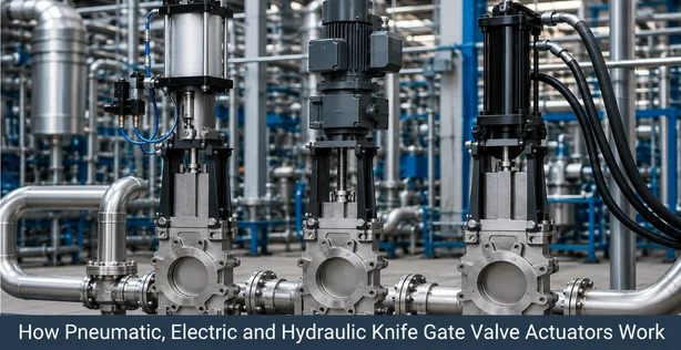
Actuation method is one of the most important decisions when specifying a knife gate valve for automated service. Whether you choose pneumatic, electric, or hydraulic actuation affects operating speed, control precision, utility requirements, and long term reliability. This guide compares all three actuation types so you can match the right system to your process.
Why Actuation Matters in Knife Gate Valve Selection
A knife gate valve can be operated manually, but most industrial installations use an actuator for remote, repetitive, or automated operation. The actuator type determines how fast the gate opens and closes, how much force it can apply, how it fails during a power or air loss, and what utilities need to be available at the valve location. Choosing the wrong actuation method can lead to slow cycle times, higher maintenance costs, or safety risks in critical isolation service.
What Is a Pneumatic Knife Gate Valve?
A pneumatic knife gate valve uses compressed air to drive a piston actuator that raises and lowers the gate. Pneumatic actuators are widely used because they offer fast cycle times, simple construction, and reliable fail safe options such as spring return to close or open on air loss. They are common in slurry, mining, and wastewater applications where a compressed air supply is already available on site.
What Is an Electric Knife Gate Valve?
An electric knife gate valve uses a motorized actuator, typically with a gearbox, to drive the gate through a lead screw or similar mechanism. Electric actuation is preferred where compressed air is not readily available, or where precise positioning and integration with a plant control system is required. Electric actuators can provide accurate throttling control in addition to simple open and close functions.
What Is a Hydraulic Knife Gate Valve?
A hydraulic knife gate valve uses pressurized hydraulic fluid to move a cylinder actuator connected to the gate. Hydraulic actuation delivers the highest force output among the three options, making it suitable for large diameter valves, high pressure slurry lines, and applications where the gate must overcome significant resistance from packed or settled solids.
How Pneumatic, Electric and Hydraulic Actuators Work
- Hydraulic actuators use pressurized oil, often in the range of 100 to 200 bar, acting on a cylinder to produce significantly higher force per unit size compared to pneumatic or electric systems.
- All three actuator types connect to the valve stem through a yoke or bracket, translating actuator motion directly into gate travel.
Pneumatic vs Electric vs Hydraulic Knife Gate Valve: Key Differences
| Parameter | Pneumatic | Electric | Hydraulic |
|---|
| Power source | Compressed air | Electrical supply | Hydraulic fluid under pressure |
| Force output | Moderate | Moderate | High |
| Cycle speed | Fast | Moderate | Moderate to fast |
| Control precision | Basic open/close, limited throttling | Precise positioning and throttling | Precise with proportional valves |
| Fail safe options | Spring return standard | Battery backup or manual override | Accumulator backup |
| Typical cost | Lower | Moderate | Higher |
| Best suited for | Frequent cycling, standard duty | Remote control, precise positioning | Large valves, high resistance service |
Operating Speed and Control
Pneumatic actuators generally offer the fastest open and close times, often completing a full stroke in a few seconds, which makes them well suited for frequent cycling applications such as batch discharge or slurry diversion. Electric actuators are typically slower but provide superior positioning accuracy, useful when a valve needs to modulate flow rather than simply isolate it. Hydraulic actuators fall between the two in speed but deliver the most consistent force throughout the stroke, even against heavy or compacted media.
Automation and Remote Operation
All three actuation types support remote automation through a plant control system, but electric actuators integrate most naturally with SCADA and PLC based systems since they typically include built in positioners and feedback signals. Pneumatic systems require solenoid valves and air preparation equipment for remote control, while hydraulic systems need a power unit with pumps, reservoirs, and directional control valves, adding complexity but also delivering the most robust performance in demanding automated processes.
Power and Utility Requirements
- Pneumatic: requires a clean, dry compressed air supply, typically already available in most industrial plants.
- Electric: requires a stable electrical supply, single phase or three phase depending on actuator size, with no compressed air or hydraulic infrastructure needed.
- Hydraulic: requires a dedicated hydraulic power unit, which adds upfront cost and maintenance but is often justified for large or high force valves.
Maintenance and Reliability Considerations
Pneumatic actuators are mechanically simple, with fewer components to fail, but depend on consistent air quality, since moisture or contamination can degrade seals over time. Electric actuators require periodic gearbox lubrication and motor inspection but avoid the wear issues associated with compressed air quality. Hydraulic actuators demand the most attention, including fluid quality monitoring, seal inspection, and pump maintenance, but they also tend to have the longest service life under continuous heavy duty operation when properly maintained.
Safety and Fail-Safe Options
Pneumatic actuators most commonly use spring return mechanisms to fail closed or fail open automatically on loss of air pressure, an important safety feature in isolation service. Electric actuators typically rely on battery backup systems or manual handwheel override during a power failure, which can introduce a short delay in emergency response. Hydraulic actuators use accumulators to maintain fail safe function even during a momentary loss of pump pressure, offering a reliable safety margin for critical, high force applications.